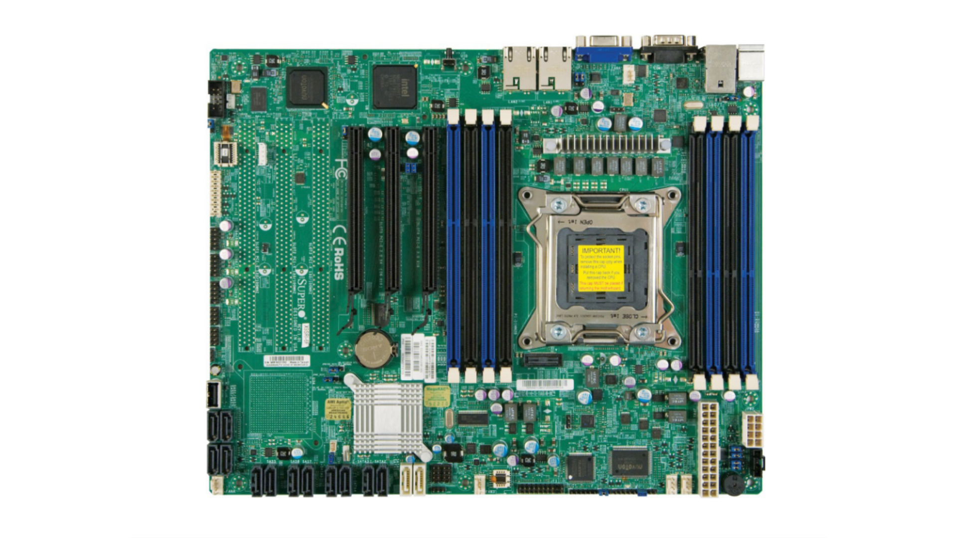
Supermicro X9SRi-F Server Motherboard
•
Platform: Intel C602 Express / Socket R (LGA 2011)
•
Form Factor: Standard ATX (12″ × 9.6″)
•
Source Authority: Supermicro Manual MNL-1284
1. Technical Overview & Key Specifications
| Category | Property | Specification |
|---|---|---|
| Board Architecture | Manufacturer & Model | Supermicro X9SRi-F (PCB Rev 1.01+) |
| Form Factor | Standard ATX (12.0″ × 9.6″ / 304.8 mm × 243.84 mm) | |
| Target Chassis | Optimized for 1U / 2U rackmount and mid-tower workstation enclosures | |
| Chipset | Intel® C602 Express Chipset (PCH) | |
| Processor Support | CPU Socket | Single Socket R (LGA 2011, 2011-pin FC-LGA) |
| Supported Families | Intel® Xeon® E5-1600 and E5-2600 series (v1 and v2 with BIOS update) | |
| Thermal Design Power | Up to 135W TDP support; 6-phase switching VRM | |
| Bus Interconnect | Intel® QuickPath Interconnect (QPI) up to 8.0 GT/s; DMI 2.0 (20 Gb/s full duplex) | |
| Memory Subsystem | Channels & Slots | Quad-Channel memory bus across 8 × 240-pin DIMM slots |
| Max Capacity (RDIMM/LRDIMM) | Up to 256 GB ECC Registered DDR3 (using 32 GB modules) | |
| Max Capacity (UDIMM) | Up to 64 GB ECC / Non-ECC Unbuffered DDR3 (using 8 GB modules) | |
| Frequencies & Voltages | 1600 / 1333 / 1066 / 800 MHz; 1.5V standard and 1.35V low-voltage DDR3L | |
| Expansion Slots | Slot 6 (PCIe 3.0 x16) | 1 × PCI-Express 3.0 ×16 physical & electrical (CPU root port) |
| Slot 4 (PCIe 3.0 x8 in x16) | 1 × PCI-Express 3.0 ×8 electrical in ×16 physical slot (CPU root port) | |
| Slot 5 (PCIe 2.0 x4 in x16) | 1 × PCI-Express 2.0 ×4 electrical in ×16 physical slot (PCH C602 port) | |
| Storage Ports | SATA 3.0 (6.0 Gb/s) | 2 × SATA 3.0 ports (I-SATA0, I-SATA1; White headers), RAID 0, 1, 5, 10 |
| SATA 2.0 (3.0 Gb/s) | 4 × SATA 2.0 ports (I-SATA2 to I-SATA5; Black headers), RAID 0, 1, 5, 10 | |
| SATA DOM Support | 1 × Disk on Module (DOM) 5V Power Connector (JSD1) |
|
| Networking & IPMI | Host Ethernet | Dual Intel® Powerville Gigabit Ethernet controllers (LAN1, LAN2 RJ45) |
| Out-of-Band Management | Integrated IPMI 2.0 with Dedicated LAN port (Realtek RTL8201N PHY) | |
| Baseboard Management (BMC) | Nuvoton WPCM450 Server Management Controller with Virtual Media & KVM-over-IP | |
| Graphics & Super I/O | Integrated Video Engine | Matrox® G200eW 2D graphics core embedded in Nuvoton BMC (1 × rear DB15 VGA) |
| Super I/O Controller | Winbond / Nuvoton NCT6776F Super I/O for LPC hardware telemetry and COM UART |
2. Motherboard Architecture & Chipset Profile
Intel C602 PCH Architecture
- Platform Controller Hub: Intel® C602 (Patsburg) dedicated server chipset.
- Interconnect: Direct Media Interface (DMI 2.0) operating at 20 Gb/s full duplex to the processor.
- Virtualization: Full hardware support for Intel® VT-d (Directed I/O) and Intel® I/O Acceleration Technology (I/OAT).
- Security: Intel Trusted Execution Technology (TXT) support.
Firmware & Power Regulation
- BIOS Device: 64 Mb SPI Flash EEPROM with AMI BIOS®.
- Standards: UEFI, SMBIOS 2.3, ACPI 1.0/2.0, PCI 2.2, DMI 2.3, Plug-and-Play (PnP).
- Console: Serial Console Redirection via COM1 / COM2 for headless rack control.
- Power Inlets: 24-pin ATX Main Power (
JPW1) plus 8-pin 12V CPU Power (JPW2).
3. Processor Support & Socket R (LGA 2011)
Processor Compatibility & Socket Topography
The Supermicro X9SRi-F utilizes a single Socket R (LGA 2011) socket designed for high-density enterprise computing. It accepts Sandy Bridge-EP (Xeon E5-1600 / E5-2600 v1) and Ivy Bridge-EP (Xeon E5-1600 v2 / E5-2600 v2) processors, featuring integrated quad-channel memory controllers and 40 direct PCI Express 3.0 lanes from the processor die.
| Processor Series | Microarchitecture | Lithography | Core Range | Max Memory Speed |
|---|---|---|---|---|
| Xeon E5-1600 / E5-2600 (v1) | Sandy Bridge-EP | 32 nm | 2 to 8 Cores (4 to 16 Threads) | DDR3-1600 |
| Xeon E5-1600 v2 / E5-2600 v2 | Ivy Bridge-EP | 22 nm | 4 to 12 Cores (8 to 24 Threads) | DDR3-1866 / 1600 |
4. Memory Subsystem & Quad-Channel Architecture
Max Registered Memory (RDIMM)
256 GB
8 × 32 GB DDR3 Registered ECC / LRDIMM
Max Unbuffered Memory (UDIMM)
64 GB
8 × 8 GB DDR3 Unbuffered ECC / Non-ECC
Memory Bus Architecture
Quad-Channel
4 Channels × 2 DIMMs per Channel
Physical DIMM Slot Layout (Quad-Channel Topology)
+---------------------------------------------------------------------------------------+
|                    SUPERMICRO X9SRi-F QUAD-CHANNEL MEMORY LAYOUT                      |
|                                                                                       |
|   [ CHANNEL 1 (CH A) ]               [ CHANNEL 2 (CH B) ]                             |
|    - P1-DIMM1A (Primary Blue)         - P1-DIMM2A (Primary Blue)                      |
|    - P1-DIMM1B (Secondary Black)      - P1-DIMM2B (Secondary Black)                   |
|                                                                                       |
|                             [ CPU SOCKET R (LGA 2011) ]                              |
|                                                                                       |
|   [ CHANNEL 3 (CH C) ]               [ CHANNEL 4 (CH D) ]                             |
|    - P1-DIMM3A (Primary Blue)         - P1-DIMM4A (Primary Blue)                      |
|    - P1-DIMM3B (Secondary Black)      - P1-DIMM4B (Secondary Black)                   |
|                                                                                       |
|   Population Order: Populate Blue slots first (1A, 2A, 3A, 4A) for Quad-Channel mode. |
+---------------------------------------------------------------------------------------+
|                MAX CAPACITY: 256 GB ECC RDIMM / LRDIMM (8 x 32 GB)                    |
+---------------------------------------------------------------------------------------+| Memory Type | Supported Module Sizes | Max Theoretical RAM | Operating Voltage |
|---|---|---|---|
| Registered DDR3 (RDIMM) | 2 GB, 4 GB, 8 GB, 16 GB, 32 GB | 256 GB (8 × 32 GB) | 1.5V / 1.35V (DDR3L) |
| Load-Reduced DDR3 (LRDIMM) | 8 GB, 16 GB, 32 GB | 256 GB (8 × 32 GB) | 1.5V / 1.35V (DDR3L) |
| Unbuffered DDR3 (UDIMM) | 1 GB, 2 GB, 4 GB, 8 GB | 64 GB (8 × 8 GB) | 1.5V / 1.35V (DDR3L) |
5. PCI Express Expansion & Bus Topology
The Supermicro X9SRi-F features three full-length PCI Express slots designed for enterprise add-on cards, high-speed storage controllers (HBAs), and compute accelerators. Unlike the legacy-focused X9SRE variant which incorporates 64-bit PCI-X slots, the X9SRi series is purely PCI Express:
| Slot Label | PCIe Generation | Physical Form | Electrical Lanes | Controller Source |
|---|---|---|---|---|
| Slot 6 | PCI Express 3.0 | x16 Full Length | x16 Direct | Direct from CPU Root Complex (8.0 GT/s) |
| Slot 4 | PCI Express 3.0 | x16 Full Length | x8 Electrical | Direct from CPU Root Complex (8.0 GT/s) |
| Slot 5 | PCI Express 2.0 | x16 Full Length | x4 Electrical | Intel C602 PCH Downstream Link (5.0 GT/s) |
6. Storage Subsystem & Drive Ports
+---------------------------------------------------------------------------------------+
|                         INTEL C602 PCH STORAGE TOPOLOGY                               |
|                                                                                       |
|  [ SATA 3.0 (6 Gb/s) Ports - White Headers ]                                          |
|   +-- I-SATA0 (6.0 Gbps AHCI/RAID) ----> Primary Fast SSD / High-Throughput Storage  |
|   +-- I-SATA1 (6.0 Gbps AHCI/RAID) ----> Secondary Fast SSD / Mirror Member           |
|                                                                                       |
|  [ SATA 2.0 (3 Gb/s) Ports - Black Headers ]                                          |
|   +-- I-SATA2 (3.0 Gbps AHCI/RAID) ----> HDD / Bulk Storage Array                     |
|   +-- I-SATA3 (3.0 Gbps AHCI/RAID) ----> HDD / Bulk Storage Array                     |
|   +-- I-SATA4 (3.0 Gbps AHCI/RAID) ----> Optical Drive / Backup HDD                   |
|   +-- I-SATA5 (3.0 Gbps AHCI/RAID) ----> Optical Drive / Backup HDD                   |
|                                                                                       |
|  [ SATA DOM Power ]                                                                   |
|   +-- JSD1 (Disk on Module 5V Power) --> Direct Power for SATA Boot DOMs              |
+---------------------------------------------------------------------------------------+| Port Name | Interface Standard | Connector Color | Bandwidth | RAID Support |
|---|---|---|---|---|
| I-SATA0 / I-SATA1 | SATA Revision 3.0 | White | 6.0 Gb/s (600 MB/s) | RAID 0, 1, 5, 10 (Intel RSTe) |
| I-SATA2 to I-SATA5 | SATA Revision 2.0 | Black | 3.0 Gb/s (300 MB/s) | RAID 0, 1, 5, 10 (Intel RSTe) |
| JSD1 | SATA DOM Power | White 2-pin Header | +5V Power Delivery | Direct DOM boot module support |
7. Network Controllers & IPMI 2.0 Out-of-Band Management
Host Ethernet (Dual GbE)
- Controller: Dual Intel® Powerville Gigabit Ethernet controllers (82574L / i350 family).
- Ports: 2 × RJ45 connectors (LAN1 and LAN2) located on rear I/O.
- Features: Wake-on-LAN (WOL) support via header
JSTBY1; PXE network boot ROM; 1.5A power design.
Dedicated IPMI 2.0 Subsystem
- BMC: Nuvoton WPCM450 Server Management Processor.
- Dedicated PHY: Realtek RTL8201N dedicated Ethernet PHY over independent RJ45 management port.
- OOB Capabilities: Full KVM over IP, Virtual Media over LAN, remote power cycling, sensory telemetry.
- Diagnostics: Onboard green blinking heartbeat LED (
DP3) and chassis Unit ID (UID) push-button with blue LED.
8. Onboard Headers, Connectors & Internal USB Port
| Identifier | Header Function | Description & Pinout Context |
|---|---|---|
JUSB2 |
Internal Type-A USB 2.0 | Direct onboard Type-A port for hypervisor boot drives (Proxmox VE, VMware ESXi, TrueNAS) |
JUSB4/5, 6/7, 8/9 |
Front Panel USB Headers | Three internal 10-pin headers providing 6 front-panel USB 2.0 ports |
FAN1 ~ FAN4, FANA |
4-Pin PWM Fan Headers | Five 4-pin fan headers with tachometer status monitoring and automated PWM thermal speed control |
JCOM1 / JCOM2 |
Serial COM UART | One rear DB9 serial connector (COM1) plus one internal 10-pin serial header (COM2) |
JTPM1 |
Trusted Platform Module | 20-pin header for hardware cryptographic module and Port 80 debug display |
JPI2C1 |
Power Supply I2C / SMBus | Inter-Integrated Circuit bus communication with PMBus compliant redundant server power supplies |
JL1 |
Chassis Intrusion Header | Monitors enclosure cover status with hardware event logging in BMC event log |
9. Architectural Comparison: X9SRi-F vs. X8DAH Workstation
| Feature | Supermicro X9SRi-F (Exhibit #2957) | Supermicro X8DAH (Exhibit #2894) |
|---|---|---|
| Generation & Sockets | Single Socket R (LGA 2011) – Romley Platform | Dual Socket B (LGA 1366) – Tylersburg Platform |
| Chipset Architecture | Single Intel® C602 Platform Controller Hub | Dual Intel 5520 IOH + ICH10R Southbridge |
| Memory Topography | Quad-Channel DDR3 (up to 256 GB, 1600 MHz) | Triple-Channel DDR3 per socket (up to 240 GB, 1333 MHz) |
| PCIe Bus Standard | PCI Express 3.0 (8.0 GT/s, direct CPU integration) | PCI Express 2.0 (5.0 GT/s, routed via 5520 IOH) |
| SATA 6 Gb/s Ports | 2 × Native SATA 3.0 (6 Gb/s) Ports | None native (All 6 ICH10R ports are SATA 2.0 3 Gb/s) |
| Remote IPMI Engine | Dedicated IPMI 2.0 LAN with Virtual KVM (WPCM450) | Matrox 2D VGA only (requires add-on SIMLP for IPMI) |
10. Curator’s Assessment & Homelab Applicability
- Homelab Workhorse Efficiency: The X9SRi-F represents the sweet spot of enterprise server longevity. Its standard ATX dimensions fit standard desktop and rackmount cases without requiring proprietary chassis adapters.
- High-Density Virtualization: With support for 256 GB of registered DDR3 RAM in a single-socket configuration, this motherboard delivers exceptional memory capacity per watt for Proxmox VE, TrueNAS CORE/SCALE, or VMware ESXi virtualization.
- Native PCIe 3.0 Bandwidth: Direct CPU PCIe 3.0 lanes ensure full bandwidth for modern NVMe adapter cards, 10GbE SFP+ networking controllers, or SAS3 12Gb/s host bus adapters (HBAs).
- Headless Out-of-Band Reliability: The onboard dedicated IPMI 2.0 interface and internal Type-A USB hypervisor header make the X9SRi-F an ideal zero-maintenance remote appliance.